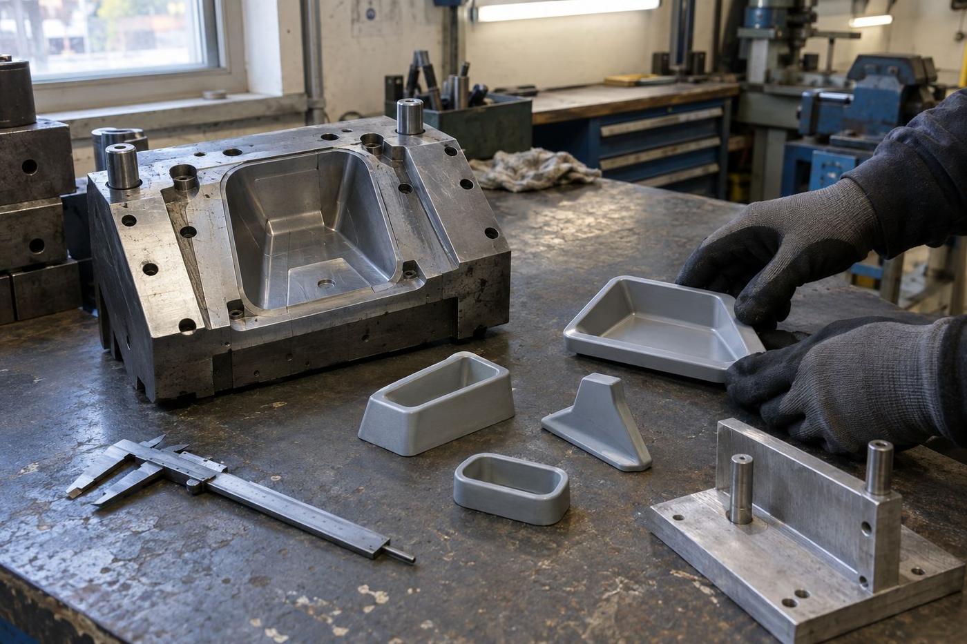
Tolerances tighter than they need to be
Very tight tolerances on features that don't need them add cost with no benefit. We suggest relaxing them where the assembly will accept it.
DFM guide for OEM designers
Most silicone parts are designed by someone who's designed one before. If this is your first, or if the last one taught you nothing you'd want to repeat, here's what to think about while the design is still on the screen.
The premise
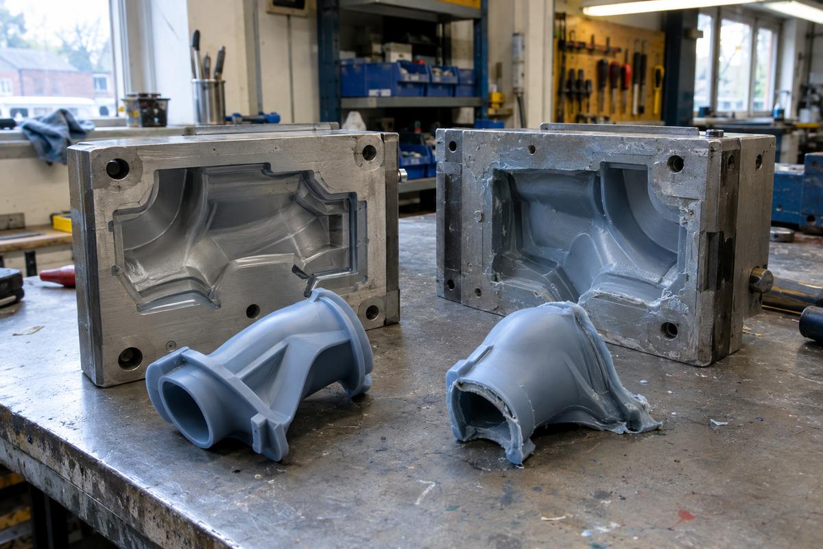
A flexible silicone tool can produce almost any shape you can draw. That's why prototype silicone parts often look great — the tool bent, stretched, or was manipulated by hand to release the part.
At volume, none of that is available. A production tool releases the part with a defined ejection mechanism, on cycle time, without human intervention. Features that were fine in prototype start to cost money in labour, reject rate, or tool wear.
Designing a silicone part with volume in mind from the start doesn't restrict what you can make — it means the same design works at prototype and at production without redesign. That's what this guide is about.
Geometry basics
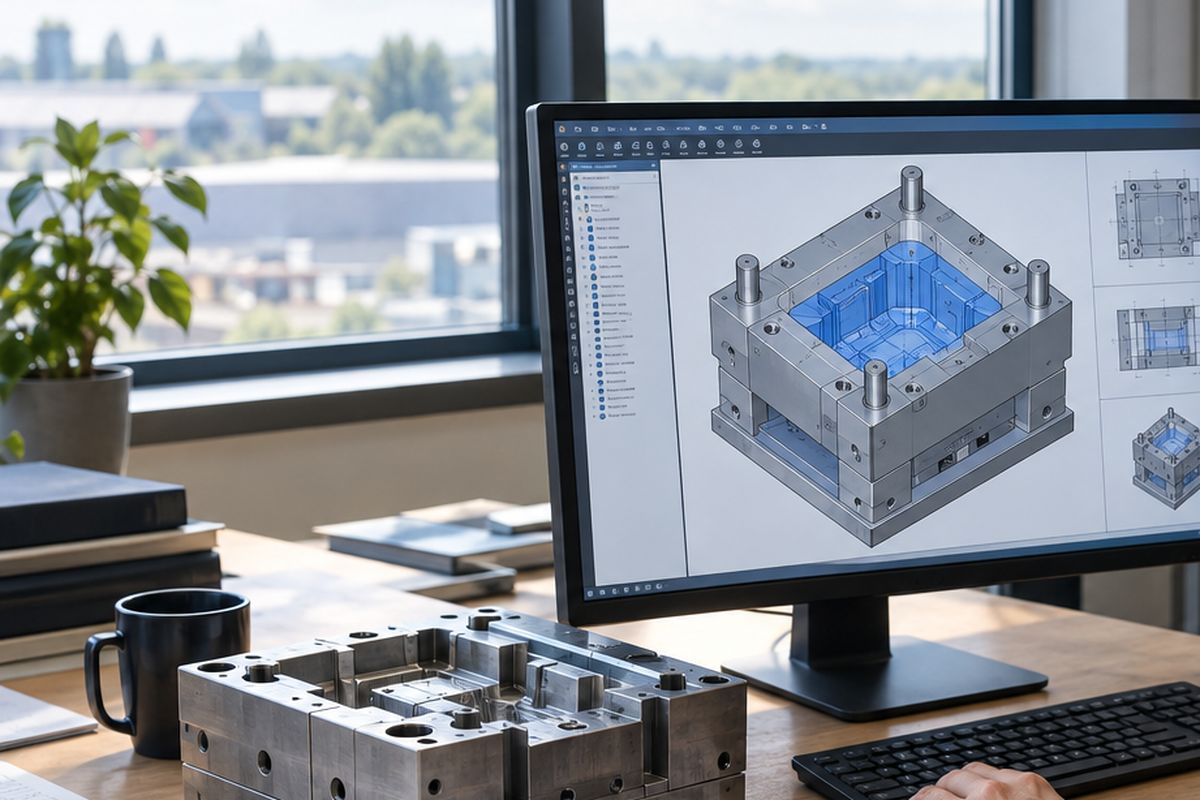
Silicone releases best from tools designed with release in mind. Small changes here save more cost than any other DFM detail.
Even a couple of degrees of taper on every wall parallel to the pull direction makes release dramatically cleaner. Straight walls drag on every cycle.
An undercut requires the tool to split at that feature. Every additional split line adds tool cost and adds a witness line on the part.
Sharp internal corners concentrate stress in the silicone and trap material during release. A small radius costs nothing and prevents tears.
Where the ejector pins land will leave marks. Route the ejectors to a face you don't care about, ideally before the tool is drawn.
Cross-section
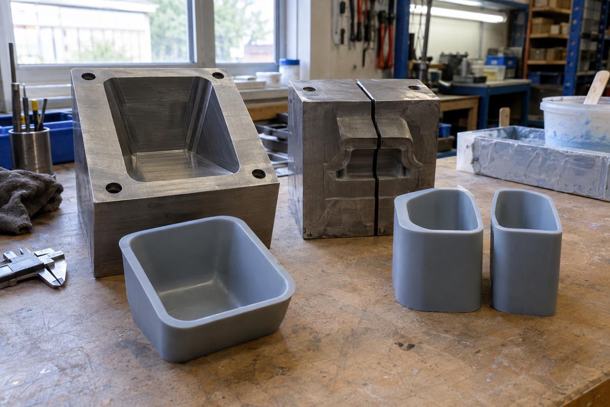
Even walls cure uniformly. Thick sections cure last and control cycle time — a small thick section can double the cycle for the whole part.
Where thin meets thick, the material will flash across the thin section during cure. Design the transition to be gradual or move the parting line.
Where a stiff feature is needed, ribs and gussets stiffen the part without adding curing time or material cost.
Where flash lands
These decisions are made once, in the tool design, and travel with every part for the tool's lifetime. Worth getting right.
Cosmetic, sealing, skin-contact — none of these should have the parting line running across them. Move the parting line to a face you don't care about.
The gate leaves a mark. Locate it on the underside of the part, or on a feature that will be hidden in assembly.
Air pockets prevent complete fill. Design vents into the tool at any high point of the cavity. Vents leave small witnesses — put them where you can accept them.
For compression especially, cut a defined flash groove so surplus material lands somewhere predictable rather than feathering across the part.
Our process
Very tight tolerances on features that don't need them add cost with no benefit. We suggest relaxing them where the assembly will accept it.
Cavities with a single high point that isn't vented will fill inconsistently. Easier to fix in CAD than to work around in the tool.
Anywhere thick meets thin sharply, we flag it. Small design changes prevent flash and reduce cycle time.
Features designed for one assembly method that add moulding cost. We check what the assembly team actually needs before locking the tool in.
Keep reading
A moulded part isn't always a finished part. Understanding what happens between the press and the shipment helps you specify the…
Read the guideFor anything a customer will see, colour is one of the two things they judge (feel is the other). Getting the colour right is…
Read the guideYour product is real. You've made prototypes, maybe pilot runs. The design is stable and the volume forecast is starting to be…
Read the guideAt a glance
Which route suits your quantity
Swipe to see the whole diagram
Get in touch
Rough annual volume, target unit price, and any deadlines. That's enough to work out whether compression, LSR injection or something else is the right tool.
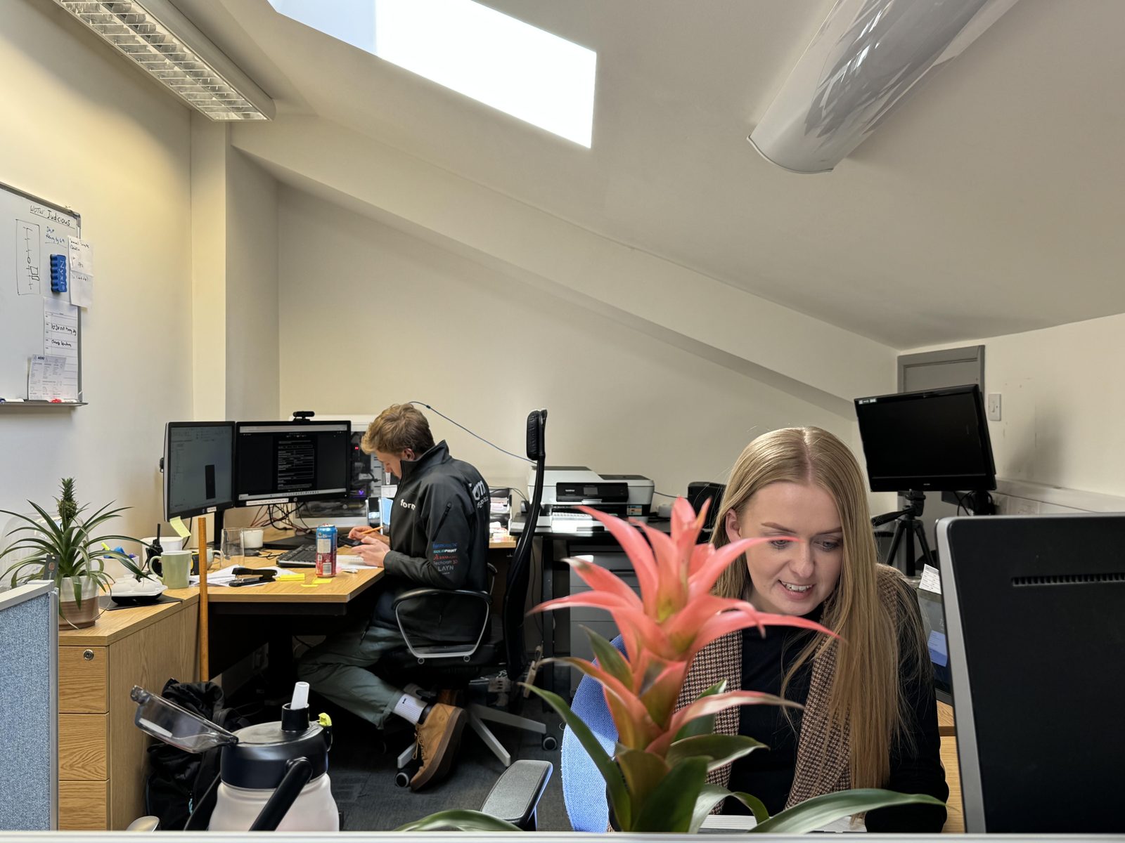
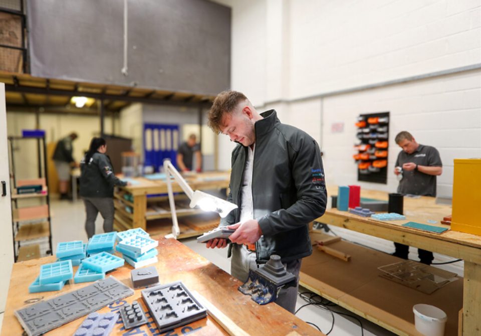
Real people, a real workshop
No call centre and no middlemen. When you contact TCI Products, you speak to the team who design, build and check your mould.

 Thomas LaneManaging Director
 George PrestonDesign & Project Manager
 Kelly BallingerHead of Partnerships
 Jim AndertonProduction Manager
 TheodoreEmployee Welfare